A return to normal service this week, as we take a look at how to laser cut cardboard with some tips and tricks along the way.
There are a large number of applications that cardboard can be used for; from presentation boxes to gaming landscapes and prototypes. So it’s a useful material to learn how to process properly.
As its been a while since we looked at day to day running , so we thought it might be useful to revisit machine set up and how to select laser parameters as well as cutting orders in RDworks. Our tame superuser, will talk you through this in the intro to todays video as we look at how best to process cardboard.
Interestingly, one of the most common questions we are asked by customers during laser demonstrations at Thinklaser, is in relation to the burn around the cut edge on materials such as card and wood. Can it be removed and how do I prevent it?
Russ demonstrates and quick and simple method to reduce the burn on your parts and how to test and compare cutting parameters. I’ll leave this to the master to explain as a picture paints a thousand words, but its easier than you think.
One element of todays tutorial that is worth delving into in more detail is the difference between lens’. The Lightblade is supplied with 2”, 2.5” and 4” lens’, what’s the difference and what is the benefit?
The correct lens for the correct application.
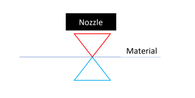
Essentially as you change the lens, you modify the focal depth and the focal profile coming out of the nozzle. Please forgive the second rate artwork but I’ll explain below:
A 2” lens will create a profile from the nozzle that looks like this:

The red and the blue triangles represent the Hot and Cold side of the beam (before and after the material). You can see the focal triangle is short and fat, as a consequence it narrows and widens in a short vertical distance.
If you were to look at a 4” lens, the focal profile will look something like this:

This beam profile is the same width but much taller, as a consequence the beam width requires more vertical distance to fatten, or if you were paying attention in previous blogs, reduce its spot density.
The upshot of this is that if you have a short fat beam, it’s great for creating a high energy spot that will quickly dissipate in density as you change Z position – so perfect for thin materials. Whereas if you have a long (apparently thinner) beam profile, the spot density remains constant for longer and so the energy density is higher over a larger distance in the Z, or, great for thicker materials.
This change in focal profile is the reason why, as you will see in the tutorial, that cutting can be affected by an uneven bed, as the 1.5” lens is a more extreme version of the 2”, the window of operation in the Z axis is even smaller – hence the issues Russ has been having.
Anyhow – project time. The files are here: https://we.tl/t-HY6kA0uSgO
This weeks learning lab can be found on our youtube channel here:
If you have any questions about this blog or are looking to purchase a Laser cutting system, please don’t hesitate to get in touch and ask one of our friendly experts for advice, you can reach us on 01737 826902 or at info@thinklaser.com.
