Scan field calibration is why two identical markers produce different parts
A galvanometer draws on a curved, distorted field. Correction files make it look flat, and those files are machine-specific, lens-specific and perishable.
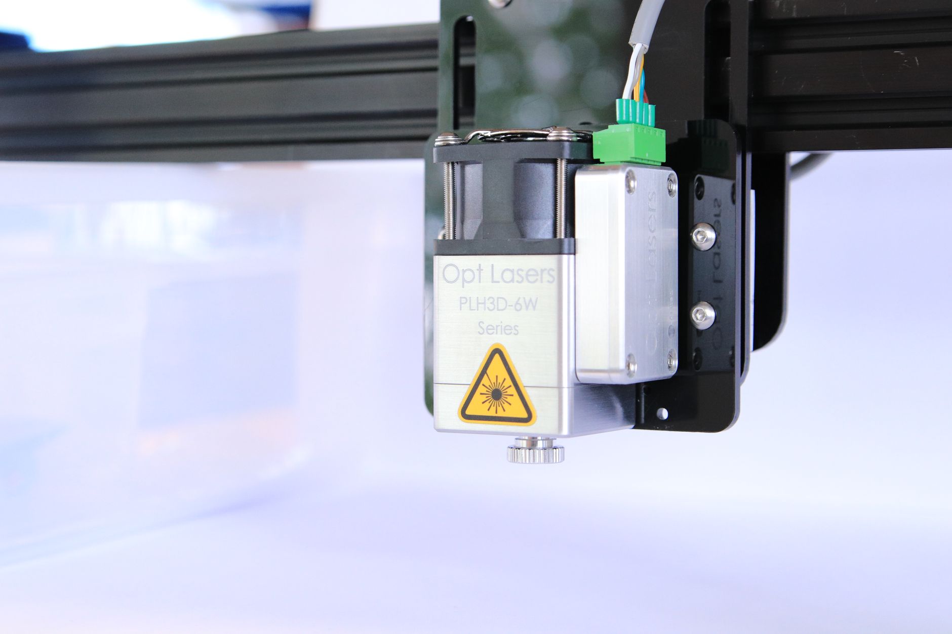
Two mirrors deflecting a beam through an f-theta lens do not produce a flat, square, uniformly scaled field. They produce a pincushion-distorted field on a curved focal surface, with scaling that varies across it. Everything a marking system does to appear accurate is correction applied on top of that.
What correction files do
A correction file maps commanded coordinates to the deflection angles that actually put the spot where it was asked to go. It is generated by marking a grid on a calibration target, measuring the real positions, and computing the transformation.
The file is specific to the combination of scanner, lens, working distance and wavelength. Swapping to a lens with a different focal length invalidates it entirely. So does moving the head relative to the work surface.
Why it drifts
Correction is not permanent. Galvanometer scanners heat during operation and their gain changes slightly. Mechanical mounts shift after a collision or a shipping event. Lens changes, protective window replacement and any adjustment to head height all move the relationship.
The symptom is subtle: marks that are legible but slightly out of position or scale, growing worse toward the field edges. It rarely announces itself as a failure, which is why it is often discovered when a customer measures a part.
Where it matters most
Applications where mark position is a specified dimension — alignment features, marks that must sit within a bounded area, codes that must register with a printed layer — feel this immediately. Applications where the mark just needs to be readable often never notice.
Practical control
Shops with accuracy requirements verify field calibration on a schedule using a measured target rather than a visual check, keep correction files under version control alongside the marking programs, and re-verify after any optical change or collision.
The general lesson is that a marking system's accuracy specification describes the machine on the day it was calibrated. Holding that accuracy is a maintenance activity, not a purchased property.
This article was produced by the LasersNews AI desk and reviewed by our editors.
Related reading

Traceability rules quietly reshape what a marking system has to do
Permanent part identification is no longer a finishing step — it is a data problem that happens to involve a…

UV marking found its place where heat is the enemy
At 355 nm the mark comes from breaking molecular bonds rather than melting. For plastics, glass and thin coat…

Traceability rules are now writing the marking specification
UDI, aerospace part marking and battery passports each demand a code that survives the product's life. Perman…