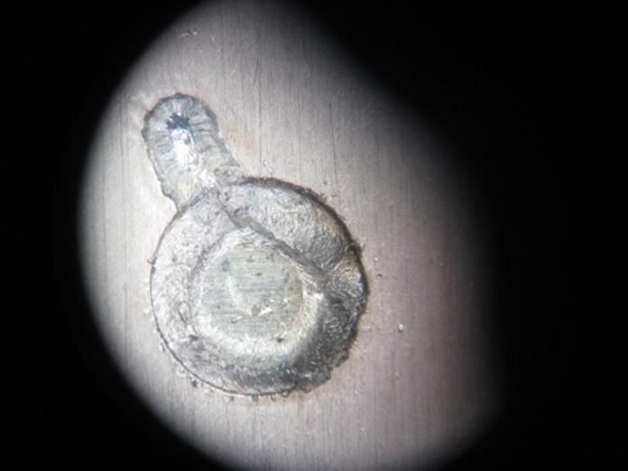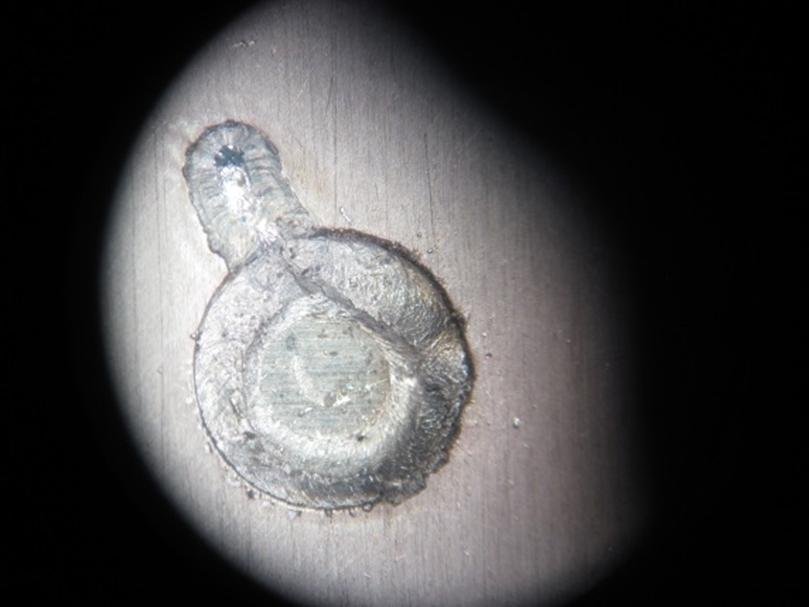
The desired welding is due to the characteristics of quality that are listed below.
Visual aspects
- Homogeneous and “acceptable surface appearance
- Absence of pores, projections and cracks on the surface
- The perpendicular sections shall show the shape of the bead and internal quality of the welding
Quantitative aspects
- Maximum penetration. > 0.x mm
- Maximum width of joint > x mm
- Welding quality measured as ohm resistance between welded part and a point at a given distance. For example, 15 mm may not exceed xx mΩ
- To try to minimize the thermal effect due to welding. To measure the temperature reached during the welding process within a given distance. This should not exceed x 0C
The idea is that after the tests, the previous aspects are defined as precisely as possible in order to proceed to the manufacture stage.
Elements used
Laser equipments
- Rofin Laser YAG FL020
- Raylase 3D Scanner Head
- Kuka Robot where we position the scanner head tool for positioning and clamping the test pieces to be welded
Elements of control and measurement
- Microscope of N increments
- Temperature measurement equipment with fast replacement thermocouple type X
- Precision resistance measurement equipment
- Equipment for cutting and chemical treatment of test pieces
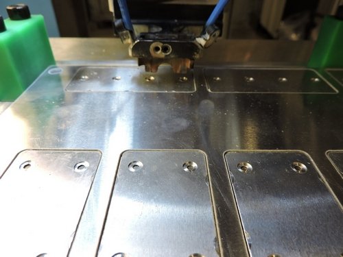
Description of laser welding test
Material: For the test, different grades and thickness of aluminum are used for the parts to be welded are the following Aluminum (Axxx1) 0.5mm thick + NIKIM XµM coating and aluminum (Axxx2) 2 mm thick. The shape of the test pieces, qualities of aluminum, coatings and thicknesses have been defined in a previous phase.
Positioning: For the positioning of the beam in the area where the welding is to be done, the laser pointer is used which emanates from the same head that the beam stops the welding. At this stage, this pointer positioning system is sufficient because it requires a great deal of precision in which the use of other means, such as artificial vision, is advised.
Focal Distance: The focal distance of our equipment is 324 mm. This has been determined based on of tests conducted at different positioning heights of the header for a same power and speed. The focal length is one in which it obtains the maximum penetration of the beam in the part where is it projected.
Type of welding and trajectory: These aspects have been defined in a testing phase that concludes with the realization of an overlapping welding of circular trajectory of 3800 with tangential output that ensures a continuous and closed bead because it allows a large welding surface area located and trying to minimize the impact of the thermal effect of the welding to other areas.
Gas: It is a question of defining the gas supply parameters, with or without gas, gas type (helium or argon), flow and angle of incidence, etc. To do this welding are done on different test pieces and it was concluded that the best conditions of appearance and penetration is achieved with the supply of argon gas. Although the result with Argon is somewhat better than with helium, the differences are minor and very subtle so that it cannot be concluded that it is inadvisable to use the helium for this type of welding.
Power and Speed: With the previous parameters already defined, welding tests are done on test pieces by combining the parameters of power and speed. The power goes from 900 W to 1,500 W, and speed between 15 and 40 mm/s. For such an error, both parameters are limited until acceptable results are given according to the desired and/or defined quality characteristics above.
Results
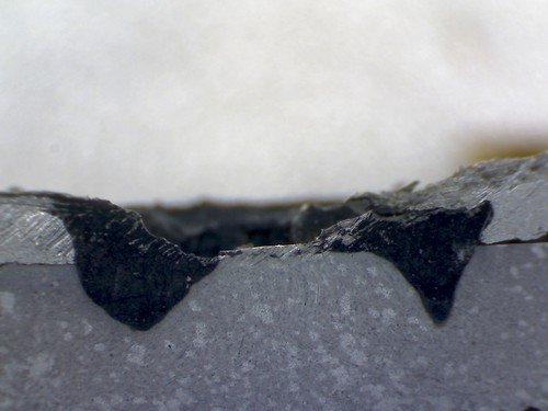
The visual aspects of the laces are observed, measured and analyzed under the microscope both the beads on the surface as on sections measuring cylinders.
The result is satisfactory.
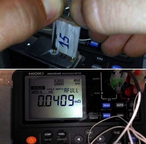
The temperature reached, at a point located between the two parts to be welded and at xx mm of the welding area, is recorded with the temperature measurement equipment and J type thermocouple.
The impedance measurement is taken between the center of the bead and another point located at a constant given distance of 10mm.
